Making an Automated, Operational Hydro-Electric Dam in Luanti
Here are some notes and pictures of how I made a working, automated hydro-electric dam in Luanti. The dam gates can be opened and closed manually to generate more or less power, or, if the power demand becomes too high or too low, the dam will automatically open or close gates to adjust the power accordingly.
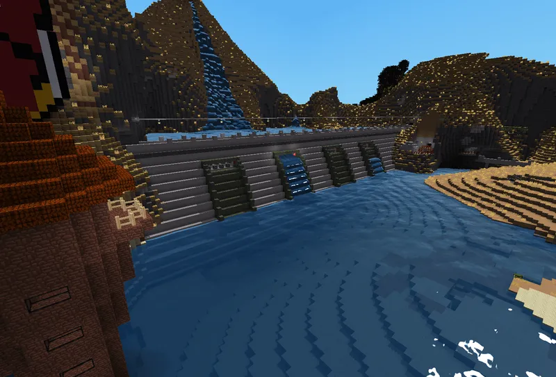
Luanti Mods in Use
I use a bunch on Luanti mods, but some key ones in use for this build are listed below:
- Technic Plus - For power generation
- Digilines - for programmable signals
- Digistuff - For some control interfaces
- Mesecons - For circuitry and programmable controllers
And many others that are dependencies of the above, and generally decent looking blocks.
Building the Dam Structure
I will leave the general design of the dam as a exercise for the reader, but in basic terms what you need is:
- A large body of water
- A big wall to hold the water back, holes cut into the wall at certain intervals where water will flow through.
- Another big wall a reasonable distance from the other one to create a large building, within which all the dam mechanics will be. Holes in the same-but-lower position as the back wall's holes to let the water out.
- Within the dam, sections built around where the water will run from the back to the front of the dam. More info on this next.
Nice to have:
- A control tower, away from the main dam, but in a location where you can see the dam
- This is where you can control the gates, and where some of the programming happens.
- Per-section control areas, for emergency cut off switches and per-section controls.
Intake Gates
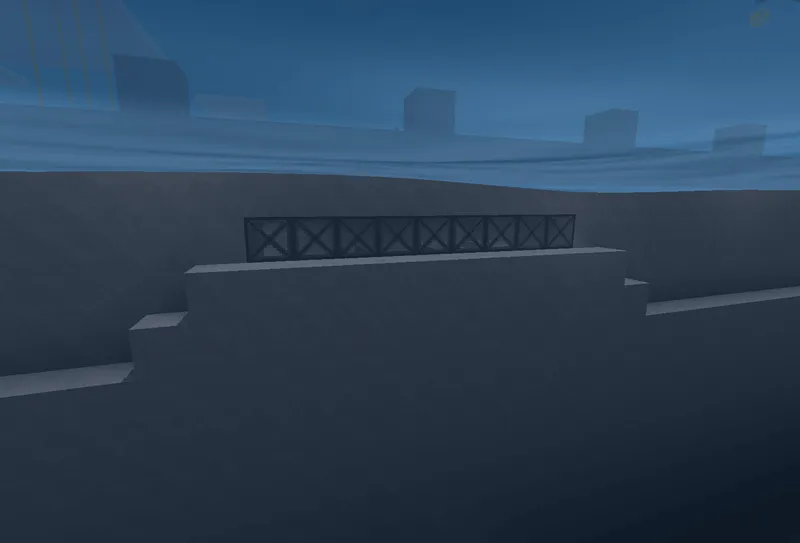
Of course, we need to control if water is allowed to flow into these generator areas, and we can do this using blocks and Mesecons Sticky Pistons. This is just a simple row of upward facing sticky pistons, with a block of your choosing on top, all connected to a mesecons wire - and a NOT gate (so no signal means the pistons are extended). More on this later.
I've put my intake gate around one block lower than the water level as I've found if it's any lower, the water just flows downwards, instead of into the intake gate.
The Generators and Generator Area
For simplicity, I'll be using Low-Voltage Hydro Generators from the Technic/Technic Plus mod, but you could easily switch these out with Mid-Voltage Hydro Generators if you wish. Or run both in parallel.
These Hydro LV Generators generate power based on water flowing past any of their 4 sides, and their efficiency changes depending on that flow. I've found an ideal efficiency build is to ensure water can flow from at least above, to at least one block below the sides of the generator. This basically means the generator will be sat on it's own wire, which acts as a pedestal to hold it up.
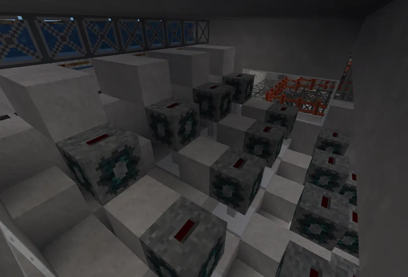
I have an array of 17 generators, in rows of 4, 4, 5 and 4, with concrete blocks in places to maximise water flow.
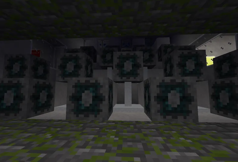
You should ensure the water flow by allowing it to drop down every couple of blocks, so each generator block would be 1 block lower and 2 blocks forward of the previous generator.
I have this duplicated 3 more times for a total of 4 different generating sections.
Switching Station
The Technic mod requires all power networks are connected to one (and ony one) switching station. My 4 hydro generator arrays all have cables coming back to a Switching Station building I have built inside the dam, which then supplies power to the rest of the world.
Programming
Where the control tower, intake gate section controls are and wiring to them is up to you. You will need a digiline wire from each intake gate control section back to the main control tower, and a bunch of luacontrollers.
Intake Gate Section
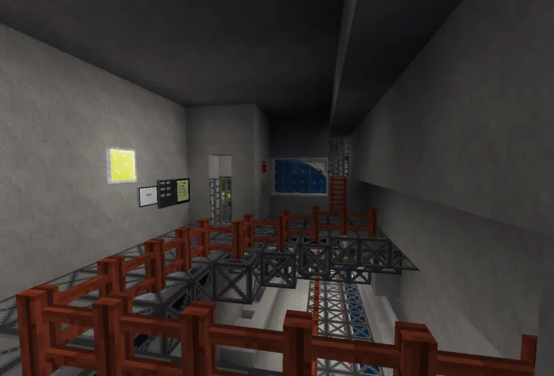
My intake gate sections consist of a luacontroller, an AND gate, a NOT gate, the sticky pistons for the gate, and a switch to act as an emergency override switch to turn that section off fully.
The setup looks something like this:
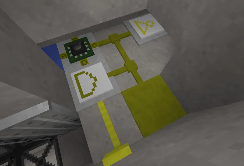
EDIT: I've removed the AND gate from my set up, as the luacontroller can handle this and also allows us to report back if the emergency switch has been triggered ("locked"). So ignore the AND gate from the image above.
Programming-wise, the luacontroller will run the below code.
gate = 1 -- ID of the Gate

-- The Control Tower luacontroller interfaces with a touch screen control.
-- When the touch screen button is pressed, the luacontroller sends a
-- "Gate {ID} Open" or "Gate {ID} Close" signal, which we use here to
-- switch port.d of this luacontroller on or off
-- If pin.d (our override switch) is off, then don't do anything here
if event.channel == "Gate "..gate.." Open" and pin.d then
  mem.status = "open"
  digiline_send("gate_status", {gate = gate, status = mem.status})
  port.c = true
elseif (event.channel == "Gate "..gate.." Close" and pin.d) then
  mem.status = "closed"
  port.c = false
  digiline_send("gate_status", {gate = gate, status = mem.status})
end

-- WHen our override switch on pin.d is triggered, set the status to locked
if event.type == "off" and event.pin.name == "D" then
  mem.status = "locked"
  port.c = false
  digiline_send("gate_status", {gate = gate, status = mem.status})
elseif event.type == "on" and event.pin.name == "D" then
  mem.status = "closed"
  port.c = false
  digiline_send("gate_status", {gate = gate, status = mem.status})
end

-- Start an interrupt cycle to run after 5 seconds
if event.type == "program" then
  mem.status = "closed"
  if not pin.d then
    mem.status = "locked"
  end
  interrupt(5,"send_status"..gate)
end

-- When the interrupt signal is received, send the current gate status to
-- the control tower.
if event.iid == "send_status"..gate then
  digiline_send("gate_status", {gate = gate, status = mem.status})
  if event.iid then
    interrupt(15,"send_status"..gate)
  end
end
Control Tower
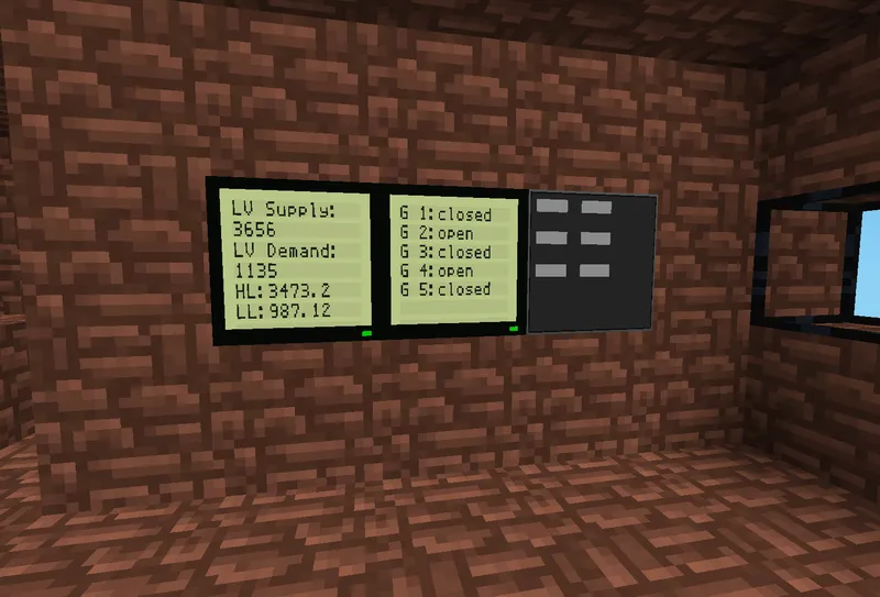 This is where the control really happens. Here we have a touchscreen with
Open/Close buttons for each gate, pressing them sends a signal to that gate's
luacontroller and the gate opens or shuts. I have an LCD screen nearby to
display the current status.
I also have the switching station connected to the digilines network, allowing for feedback of power usage, which allows for automation of opening/closing the gates.
-- If we get a gate_status signal, update the memory of that gate and
-- refresh the screen
if event.channel == "gate_status" then
  mem.gates[event.msg.gate] = { gate = event.msg.gate, status = event.msg.status}
  content = "\n\n\n\n\n\n"
  for i, gate in ipairs(mem.gates) do
    if gate.status ~= nil then
      content = content.."G "..gate.gate..":"..gate.status.."\n"
      digiline_send("gates_screen","G "..gate.gate..":"..gate.status)
    end
  end
  digiline_send("gates_screen",content.."\n")
end

-- When programming, set Unknown status to all gates
-- and configure touch screen buttons.
if event.type == "program" then
  -- Arbitrary order of gate opening I'd like. For automation.
  mem.gateorder = { 2,4,5,3,1 }
  -- Reverse over of above, for closing.
  mem.revorder = { 1,3,5,4,2 }
  digiline_send("gates_screen","Loading...")
  mem.gates = {}
  mem.gates[1] = {gate=1,status="Unknown"}
  mem.gates[2] = {gate=2,status="Unknown"}
  mem.gates[3] = {gate=3,status="Unknown"}
  mem.gates[4] = {gate=4,status="Unknown"}
  mem.gates[5] = {gate=5,status="Unknown"}

  ts = { { command = "clear" },
         { command = "set", width = 6 , height = 5 },
         { command = "add", element = "button_exit", X = 0.0, Y = 0, name = "button" , label = "Gate 1 Open"},
         { command = "add", element = "button_exit", X = 3.0, Y = 0, name = "button" , label = "Gate 1 Close"},
         { command = "add", element = "button_exit", X = 0.0, Y = 1, name = "button" , label = "Gate 2 Open"},
         { command = "add", element = "button_exit", X = 3.0, Y = 1, name = "button" , label = "Gate 2 Close"} ,
         { command = "add", element = "button_exit", X = 0.0, Y = 2, name = "button" , label = "Gate 3 Open"},
         { command = "add", element = "button_exit", X = 3.0, Y = 2, name = "button" , label = "Gate 3 Close"} ,
         { command = "add", element = "button_exit", X = 0.0, Y = 3, name = "button" , label = "Gate 4 Open"},
         { command = "add", element = "button_exit", X = 3.0, Y = 3, name = "button" , label = "Gate 4 Close"},
         { command = "add", element = "button_exit", X = 0.0, Y = 4, name = "button" , label = "Gate 5 Open"},
         { command = "add", element = "button_exit", X = 3.0, Y = 4, name = "button" , label = "Gate 5 Close"}
       }
  digiline_send("gates_touchscreen",ts)

  -- get the power status from the switching station too
  digiline_send("lv_switch_station","get")

end

-- When a touch screen button is pressed, send a
-- "Gate {ID} Open" or "Gate {ID} Close" signal to the
-- digilines network.
if event.channel == "gates_touchscreen" then
  digiline_send(event.msg.button,"")
end

-- When we get a signal back from the switching station, handle it
-- and update the screen.
if event.channel == "lv_switch_station" then
  content = "\n\n".."LV Supply: \n"..event.msg.supply.."\n"
  content = content.."LV Demand: \n"..event.msg.demand.."\n"

  -- This is the high threshold, i.e. the level we want to watch for to
  -- open another gate
  h_threshold = (event.msg.supply / 10) * 9.5
  content = content.."HL:"..h_threshold.."\n"

  -- Same as h_threshold, but the low threshold, i.e. when we want to close a gate
  l_threshold = (event.msg.supply / 10) * 2.7
  content = content.."LL:"..l_threshold
  -- it's a bit of a balancing act, as you could end up repeatedly opening and
  -- closing a gate if you're not careful.

  -- Show those numbers on screen.
  digiline_send("power_screen",content)

  -- Here's the automation:
  -- If the power supply is 0 or power demand is higher than our higher threshold
  -- check each gate from our order above, and open the next available one
  -- Likewise, if demand is lower than the lower threshold,
  -- cycle through our gates in reverse and close one.
  -- Pin D is where our Automaton On/Off Switch is connected.
  if pin.d then
    if (event.msg.supply == 0 and event.msg.demand > 0)
    or event.msg.demand > h_threshold then
    for i, v in ipairs(mem.gateorder) do
      g = mem.gates[v]
      status = g.status
      if status == "closed" then
        digiline_send("Gate "..v.." Open","")
        break
      end
    end
  elseif event.msg.demand < l_threshold then
    for i, v in ipairs(mem.revorder) do
      g = mem.gates[v]
      status = g.status
      if status == "open" then
        digiline_send("Gate "..v.." Close","")
        break
      end
    end
  end

  -- Finally, set an interrupt for 10 seconds to get the power usage
  -- from the switching station again, continually.
  interrupt(10,"get_power_status")
end

-- Send a signal to the switching station to get its power usage.
if event.iid == "get_power_status" then
  digiline_send("lv_switch_station","get")
end
My 5th Gate
You'll probably notice in the code blocks above I have a 5th gate, there's not a lot different with this one; it's controlled the same way, except the power generation is a little different.
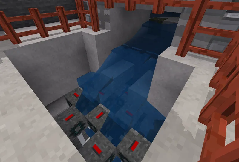
Instead of water flowing through the dam across hydrogenerators, when the gate
opens water is free to flow past the dam to a pool. In this pool
is a checkerboard pattern of hydrogenerators that the water can just about
flow over and drop between the gaps in between each generator. The efficiency isn't as good as the main dam generators (60% rather than 100%), but you could in theory use multiple layers of generators in series down one big hole to generate massive amount of power without the limitation of horizontal space.
Let it Run!
With all that in place, our dam should be operational! Run some wires,
stick some Technic Lamps up, connect some LV machines, open up a gate and
use the power and see everything (hopefully) work as desired.
You'll find if you switch all your gates off (and you don't use automation),
as the power supply gets to 0 all your lights will go out! Open a gate back up,
and power will return!
Woohoo!
If you need to run maintenance on a gate, use the emergency override to stop the water, and prevent it from being switch back on, and go in and fix what you need.
Although it is fun to watch the lights go out when the water stops flowing, you probably should put some batteries on the LV network as well, to cover you for those times no water is flowing!
Just like real life (almost)!
Block Exchange
This build is available on Block Exchange on the following link: